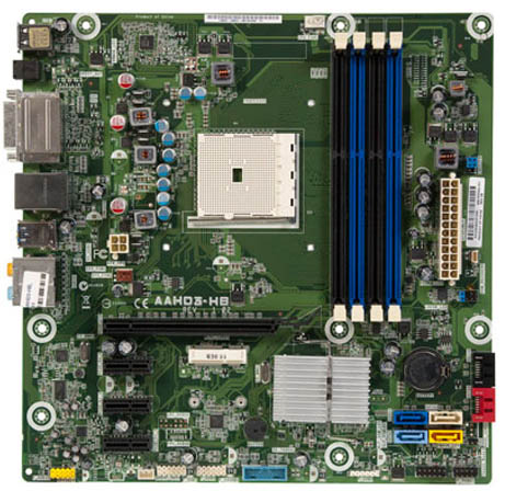
AAHD3-HB (Hibiscus) 655590-001 Motherboard BIOS Recovery / De-Bricking
Chris Bajumpaa
Welcome EEVblog viewers. ;-)
Recovering from a bad flash after the 7.16 Rev. A BIOS update.
Problem:
Sometimes (All the time?) after applying the 7.16 Rev. A BIOS update the motherboard is bricked. The following procedure shows how to de-brick.
Symptoms:
No Post.
Black Screen.
Power on with no power indicator led.
Post with keyboard error.
No usb functionality.
Unhappy user and/or machine owner.
Models affected:
HP Pav Slimline s5-1115kr PC KOR
HP Pavilion h8-1160jp AMD (Hibiscus) 3C
HP Pavilion p7-1102 Desktop PC
HP Pavilion p7-1108p Desktop PC
HP Pavilion p7-1126 Desktop PC
HP Pavilion p7-1132 Desktop PC
HP Pavilion p7-1138 Desktop PC
HP Pavilion p7-1141 Desktop PC
HP Pavilion p7-1142 Desktop PC
HP Pavilion p7-1147c Desktop PC
HP Pavilion p7-1148p Desktop PC
HP Pavilion p7-1154 Desktop PC
HP Pavilion p7-1174 Desktop PC
HP Pavilion s5-1130jp AMD (Hibiscus) 3C
Prerequisites:
- At least one HP PC with a dead AAHD3-HB 655590-001 Motherboard.
- A working Linux machine with USB.
- Arduino Uno
- Latest version of flashrom from SVN as of 4/4/2013
- serprog-duino
- avr-gcc, avr-libc, and avrdude to install serprog-duino
- AAHD3-HB Motherboard BIOS Update
Instructions:
-
Get the latest version of flashrom.
$ svn co svn://flashrom.org/flashrom/trunk flashrom $ cd flashrom && make && make install -
Get the latest verson of serprog-duino.
$ git clone git://gitorious.org/gnutoo-personal-arduino-projects/serprog-duino.git $ cd serprog-duino && make && make upload -
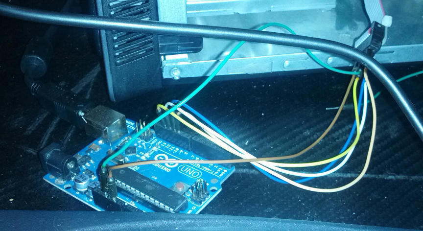
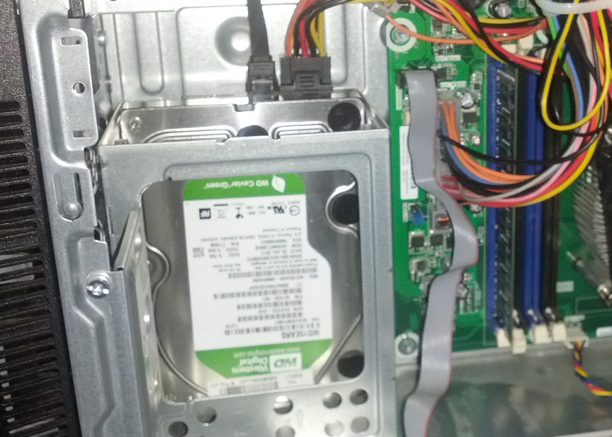
Connect the Arduino to the ROM_RECOVERY header.
I used a 10 pin female to female ribbon and some breadboard jumpers to make the connection.
The flash chip on this motherboard is a W25Q16V which is a 3.3V Part. I could only get it to flash using 5V. The motherboard was broken. It wasn't going to get anymore broken than it was. I figured I was spending a $100 bill on a replacement anyway. It was a last ditched effort and it worked for me. YMMV.
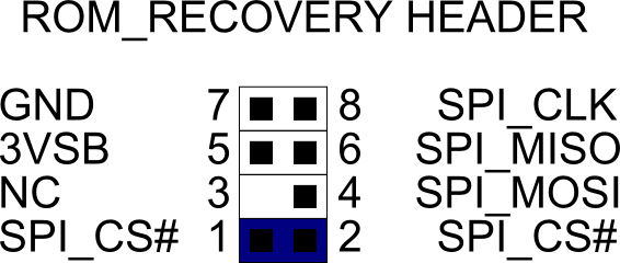
Remove the SPI_CS# jumper from the ROM_RECOVERY header. Arduino Pin 10 (SS, PORTB2) to ROM_RECOVERY Pin 1 (SPI_CS#) Arduino Pin 11 (MOSI, PORTB3) to ROM_RECOVERY Pin 4 (SPI_MOSI) Arduino Pin 12 (MISO, PORTB4) to ROM_RECOVERY Pin 6 (SPI_MISO) Arduino Pin 13 (SCK, PORTB5) to ROM_RECOVERY Pin 8 (SPI_CLK) Arduino GND to ROM_RECOVERY Pin 7 (GND) Arduino 5V to ROM_RECOVERY Pin 5 (3VSB) -
Test the connection with flashrom. If you get any kind of error check the connections above. Try swapping ROM_RECOVERY pin 4 with ROM_RECOVERY pin 6.
# flashrom -p serprog:dev=/dev/ttyACM0:2000000 -r testdump.rom flashrom v0.9.6.1-r1666 on Linux 3.2.0-39-generic (i686) flashrom is free software, get the source code at http://www.flashrom.org Calibrating delay loop... OK. serprog: Programmer name is "serprog-duino" Found Winbond flash chip "W25Q16V" (2048 kB, SPI) on serprog. Reading flash... done. -
Extract the Flash image from sp56409.exe
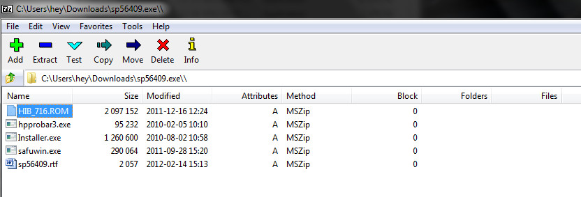
Use 7zip or whatever to extract HIB_716.ROM from sp56409.exe. -
Rewrite the flash.
# flashrom -p serprog:dev=/dev/ttyACM0:2000000 -w HIB_716.ROM flashrom v0.9.6.1-r1666 on Linux 3.2.0-39-generic (i686) flashrom is free software, get the source code at http://www.flashrom.org Calibrating delay loop... OK. serprog: Programmer name is "serprog-duino" Found Winbond flash chip "W25Q16V" (2048 kB, SPI) on serprog. Reading old flash chip contents... done. Erasing and writing flash chip... Erase/write done. Verifying flash... VERIFIED. -
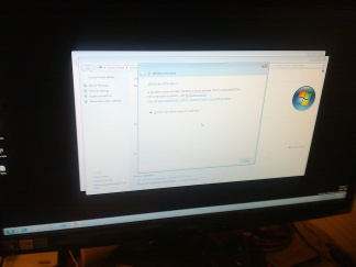
Test the machine.
Disconnect the Arduino from the ROM_RECOVERY header. Replace the jumper across SPI_CS# on ROM_RECOVERY header pins 1 & 2. Power on the Machine. -
Success! Good job.
Drink frosty beverages.